.png?width=200&height=98&name=Horizontal%20PVFARM%20Logo%20(Small).png)
What Is the Project Assets Panel?
The Project Assets panel lets you:
-
Select a subset of catalog items specific to your current project.
-
Avoid clutter from the global equipment catalog.
-
Create project-specific versions of trackers and other components.
-
Ensure consistency across project versions and team members.
Think of it like a painter's palette: You select colors from the main supply (company catalog) and arrange them on your palette (Project Assets) for easy access. You can mix and modify colors on your palette without changing what's in the supply closet. All changes SAVE automatically with the Project Version.
Where to Find It
-
Open your project in PVFARM.
-
Navigate to the left-hand toolbar.
-
Select the Project Assets tab

-
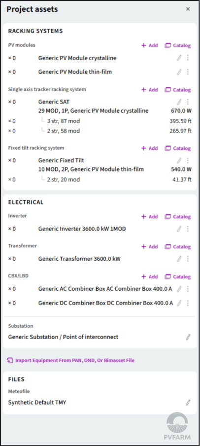
Project assets are divided into three sections :
- Racking Systems -
- PV Modules
- Single Axis Trackers
- Fixed Tilt
- Electrical -
- Inverter
- Transformer
- Combiner Boxes
- Substation
- Files -
- Meteo Data
- Racking Systems -
Using the Project Assets Panel
Add Equipment
Click “Add from Catalog” to import racking systems, inverters, or other components into your project.
If you have .PAN or .OND files for your modules or inverters, you can click "Import Equipment from PAN, OND or Bimasset File" for a quick equipment setup.
To manually set the parameters, click the pencil icon  or use the @import by AI to help you configure your equipment using a datasheet.
Create or Duplicate
- Create a tracker or fixed tilt racking system by scratch by clicking "Add".
-
You can duplicate a tracker/ fixed-tilt and rename it for a specific project version.
-
This avoids editing global catalog items and keeps projects clean.
Edit Configurations
Use the SAT/ Fixed-Tilt Wizard or equipment editors to change key details:
-
String count
-
Mounting geometry
-
Racking model or inverter brand
-
Custom names for clarity
Note: Racking editing is now only available via this panel—not directly in the 3D scene.
Single Axis Tracker Menu

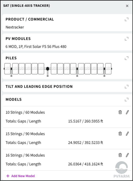
This is where you will define the information for your single axis trackers. Your trackers are displayed as a series that contains multiple lengths, or models.

This menu will open up when you click on your Single Axis Tracker equipment from the main Project Assets panel.
Product/Commercial
This is where you define the Manufacturer and Product/Series name of your racking system.

PV Modules Menu
This is where you define which module you will use in combination with your racking to create the SAT series.
- PV Module- a drop down menu containing all available PV Modules in your catalog. If you don't see the module you want, you will need to create that module or upload the PAN file for that module and add it to your catalog.
- Layout- this is where you can define how your modules are laying, in the example image the layout is set to be 1 panel wide and the panels are in portrait mode.
- Module Size, Power, and Voltage are automatically calculated based on the module information in your catalog, if these numbers look wrong please check the properties of your PV Module.
- PV Modules in String- where you can define how many modules per string
- Cold panel voltage- where you can define the cold panel voltage of your modules.
- Estimated string length is automatically calculated

Piles
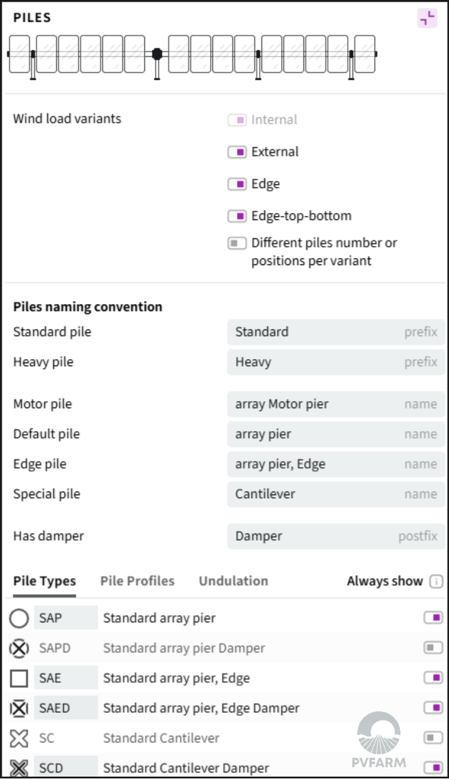
- Wind Load Variants- This is where you'll dictate which wind load variants will be available for your tracker.
- Pile Naming Convention- This is where you can manually override the name given to each pile type for your tracker.
- Pile Types/ Pile Profiles- This is where you'll choose which pile types are available for your tracker and define what profiles will be applied to those specific types.
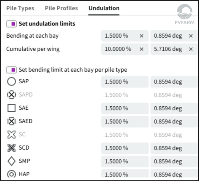
- Undulation- Set undulation limits for your trackers.
- Bending at each bay- Sets overall allowed bending limit between each pile. To configure per pile type. Turn on "Set bending limit at each bay per pile type"
- Cumulative per wind- Maximum allowed bending on either side of the motor/torque tube.
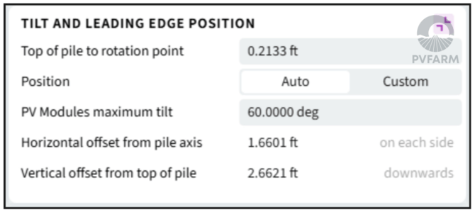
Tilt and Leading Edge Position
- Top of Pile to Rotation Point- Determines measurement from top of pile to the point of rotation for your tracker.
- Position- Toggle whether you will determine leading edge by max tilt or by horizontal and vertical offsets.
- PV Modules Maximum Tilt- This is where you'll enter the maximum amount of tilt available for your modules on your tracker.
- Horizontal offset from pile axis- This is where you'll enter the offset from pile axis on each side.
- Vertical offset from top of pile- This is where you'll enter the offset from top of pile in the downwards direction.
Models
Clicking on the pencil icon  will further expand out the specifications that can be changed for each individual model of your tracker series.
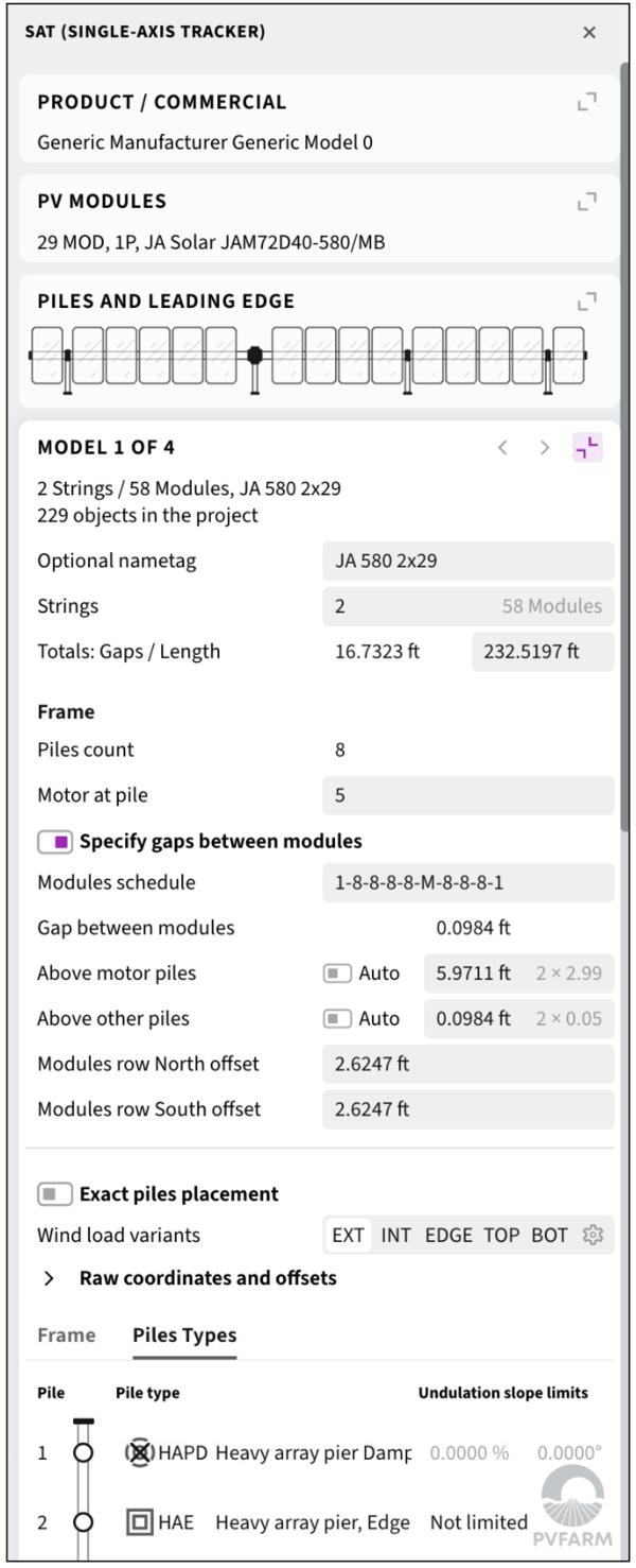
Frame
- Motor at Pile - Specifies which pile the motor will be placed on
- Specify Gaps- Toggle on or off depending on if you have different gap sizes for different types of piles,. If yes toggle on, if all gaps are the same toggle off.
- Modules Schedule- the "code" for how your SAT will be arranged, the numbers represent the count of modules, the dash represents a pile, and the M is the motor. To learn more see this article on how to create your equipment.
Exact Pile Placement- specifies the exact locations of piles on the tracker, toggle on to edit the coordinates.
Wind Load Variants- each tab represents a different wind load variant, toggle between them to see the different options.
- The settings widget allows you to turn on or off the wind load variants, also you can toggle on or off the option to have unique coordinates for each wind position.

- Frame- Gives you the coordinate information for each pile, and gives you the offsets between each pile.
- Pile Types- Allows you to define the type that is being used for each pile in the tracker, click on the type to see a drop down menu of types that are available.
Fixed-Tilt Menu
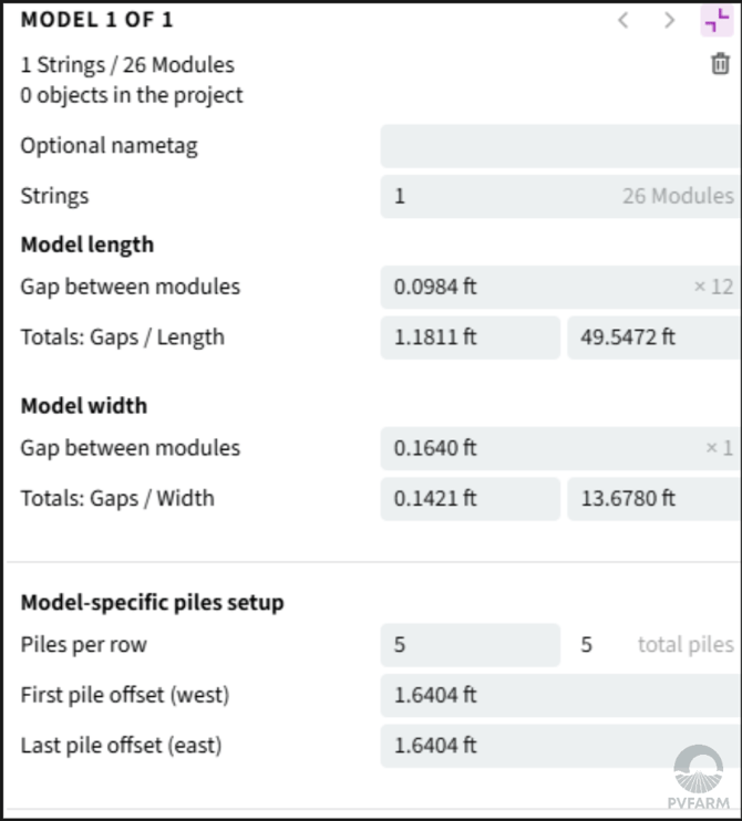
This section follows the same terminology as the Single-Axis Trackers Menu with an added change in the Models space:
- Model length- Sets the Length of the rack, tacking into account the horizontal gap between modules
- Model width- Sets the width of the rack, taking into account the vertical gap between modules
Substation Menu
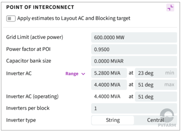
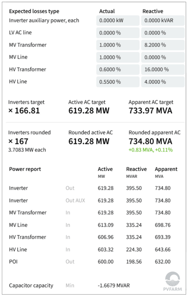
Helps you size your inverters based on POI constraints (Grid Limit, power factor, capacitor bank size) taking into account line and auxiliary loss assumptions from LV to the POI.
Point of Interconnect
Loss calculation and Power report
Inverter Loading Ratio
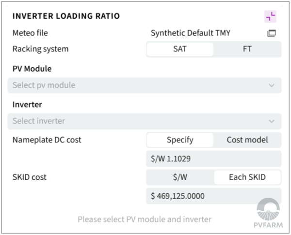
Simple ILR calculator to help you find the optimum ILR for your project based on TMY data and cost assumptions.
Meteo Data
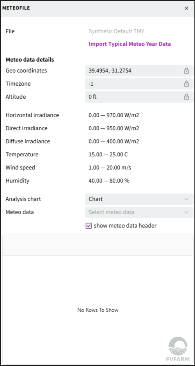
Import your Typical Meteorological year (TMY) files here. This file should contain Horizontal irradiance, Diffuse irradiance, Direct irradiance, Temperature, Humidity, and Wind speed for a typical year.
Best Practices
-
Limit your assets to only what’s required for each project to streamline layout performance.
-
Avoid editing global catalog items—always work inside Project Assets when possible.