.png?width=200&height=98&name=Horizontal%20PVFARM%20Logo%20(Small).png)
How To Draw Boundaries
-
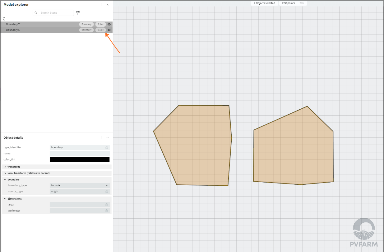
Open the Model Explorer and Object Details as an initial step
-
To set up a top-view
-
Press ‘2’ on your keyboard
-
or ‘7’ for Numpad
-
-
Plus Sign (+) on right side of screen → Boundary

-
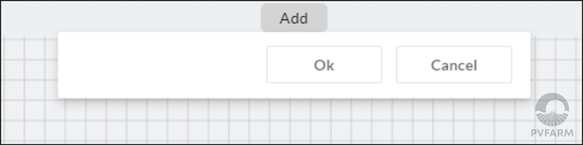
Observe that the top of your screen now says "Add". The menu is ready for your very first point of Boundary
-
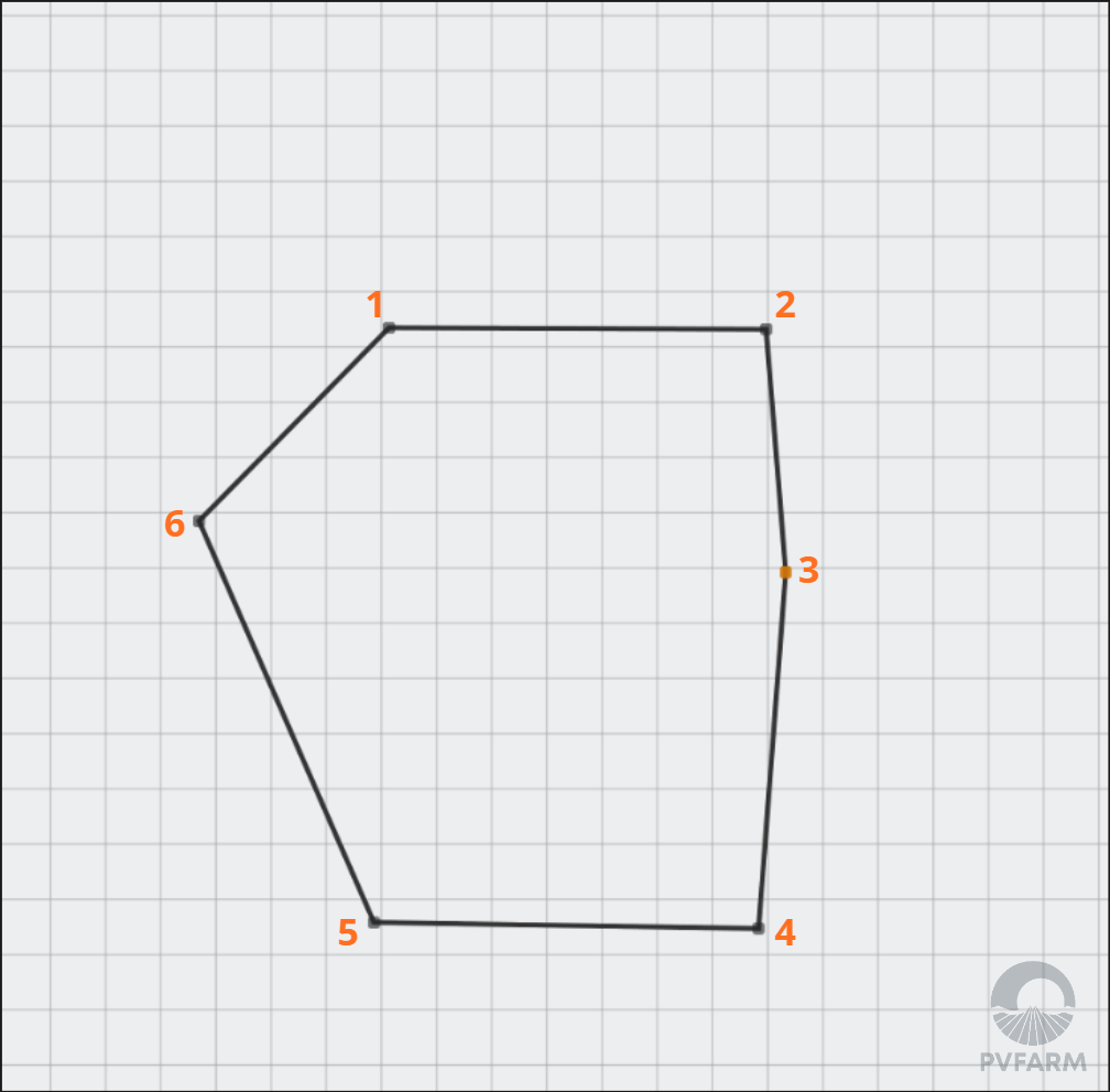
You can now begin adding points to make up your boundary
-
When you tick your very first point the Properties and Model Explorer data will be updated:
-
You’re still in the Edit mode even if you're first point isn't visible
-
’Add’ mode at the central top of your screen - to control the drawing process
-
‘Edit’ mode at the right top of your screen - to inform that points of boundary are only objects you can work with
-
-
Model Explorer shows every 3D object on the 3D scene - and your very first point starts a boundary-creation process
-
The point is selected by default so that you can observe the Properties
-
-
Properties View shows parameters for your selected 3D object
-
Every Boundary has the type (include or exclude). Initially, all boundaries are ‘include’
-
Every 3D object has the ‘Dimensions’ section
-
but for now ‘area’ and ‘perimeter’ are empty because there is no polygon yet.
-
-

-
-
Continue to add points to the View and observe the parameters are updated.
-
Zoom in/out if needed by mouse scroll

-
-
To undo a point
-
Use ‘CTRL +Z’ to cancel the very last point
-
-
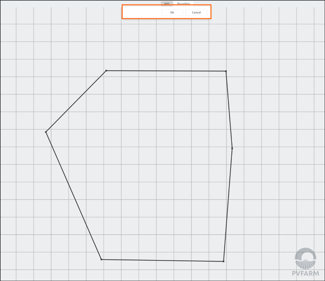
To finish the Boundary creation or editing process press ‘OK’ on the ‘Add’ menu
-
or press ‘Cancel’ to delete all your points
-
-
The ‘Add’ mode is gone but the ‘Edit’ menu is still active
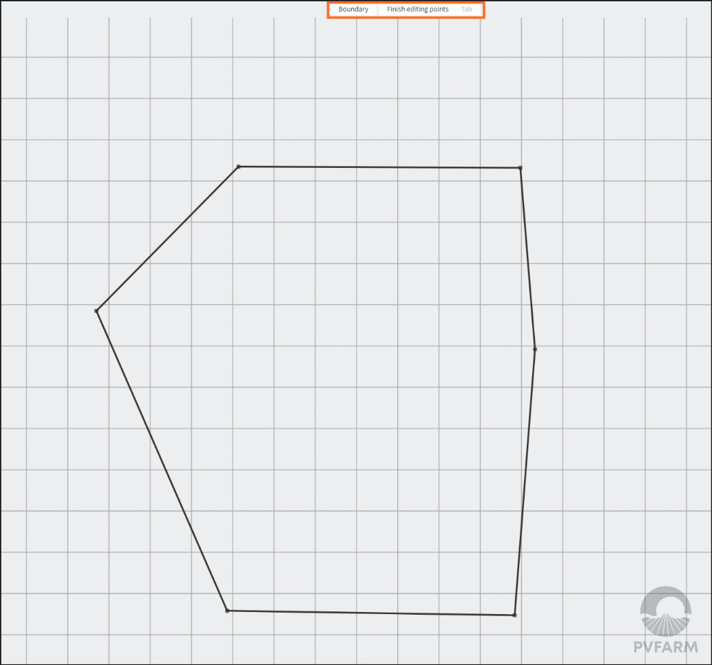
-
The ‘Edit’ menu means that you can edit a Boundary by point if needed
-
Press ‘ESC’ on your keyboard to exit the ‘Edit’ mode
-
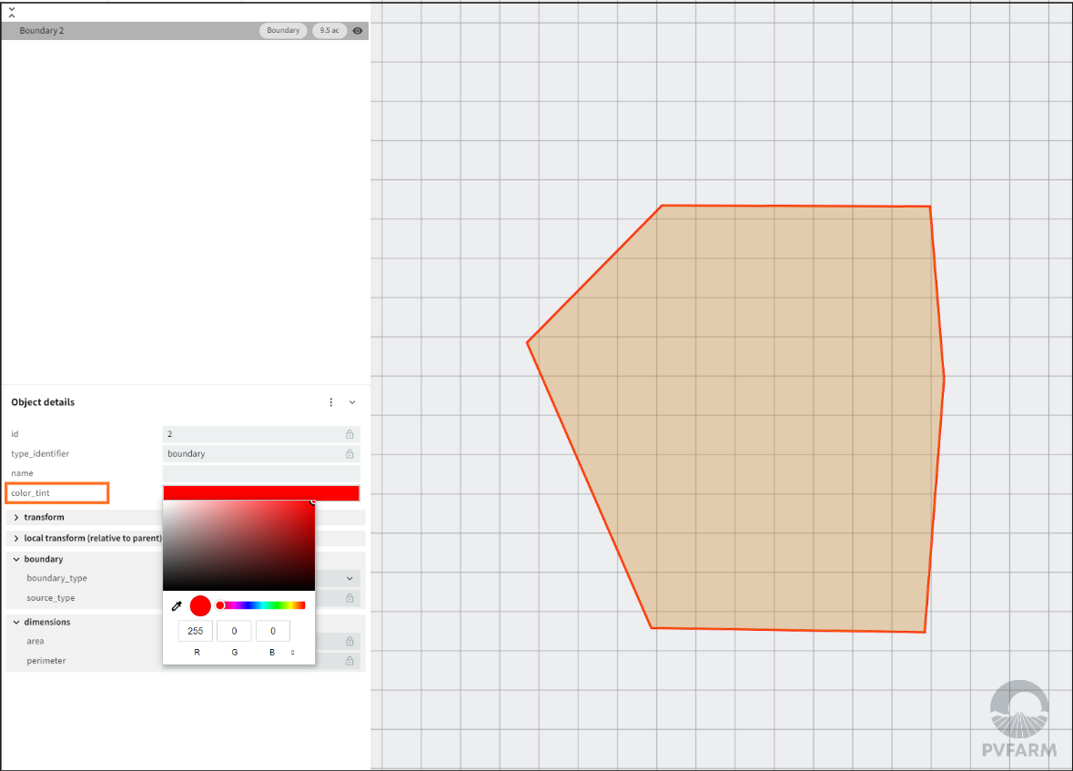
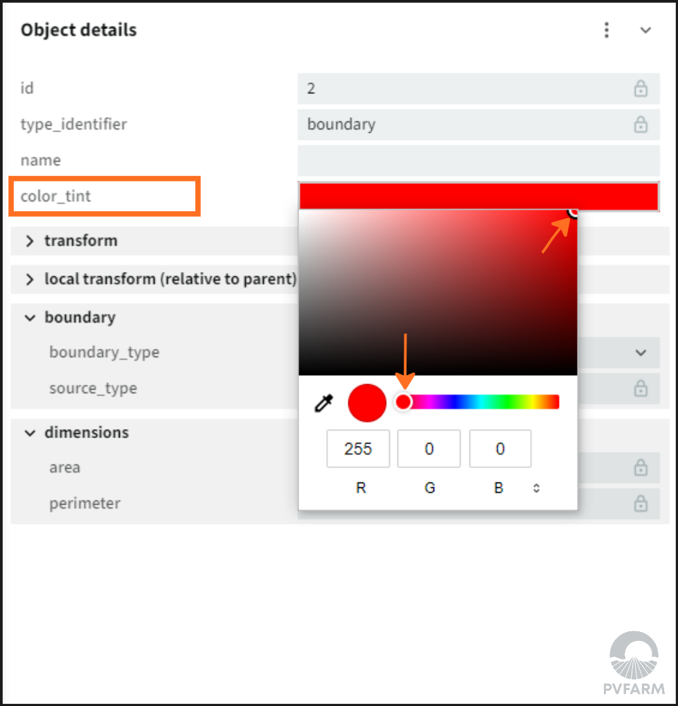
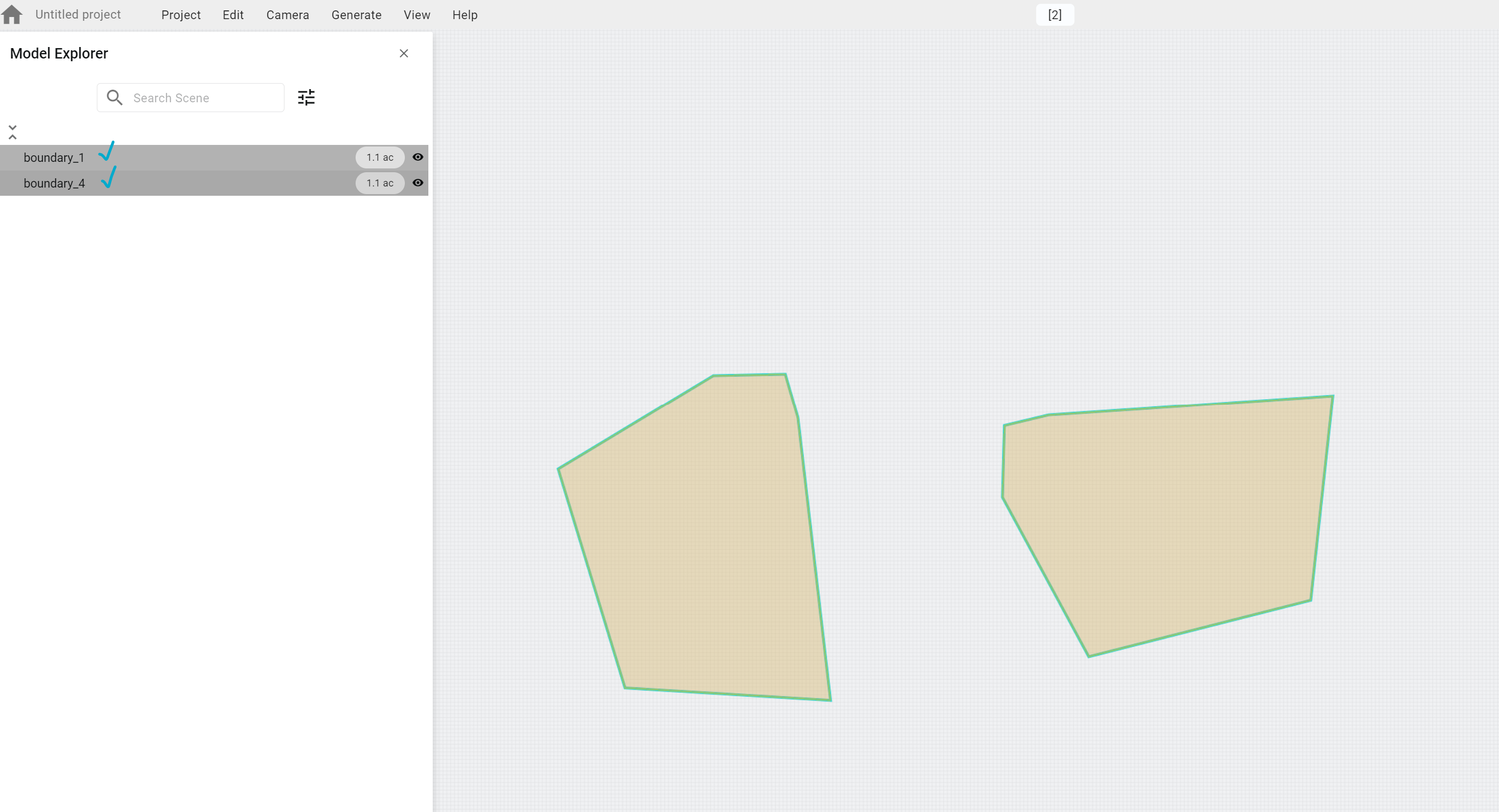
To color a Boundary
-
Select a Boundary or multi-select (via ‘CTRL’)
-
Press the ‘color tint’ space
-
Select any color you like on the color palettes or use RGB values (note a boundary will automatically turn red if you make it an exclusion zone)
-
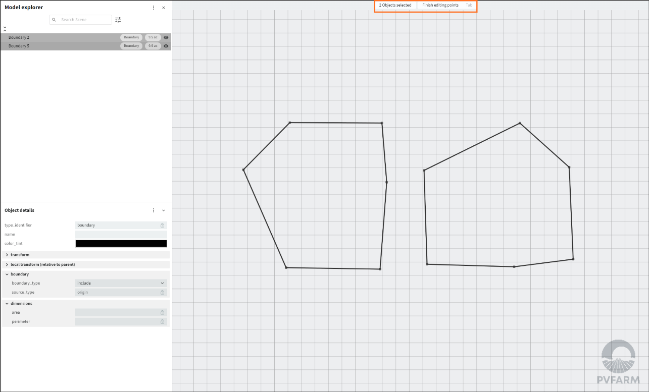
How To Edit Boundaries
-
Select a Boundary from the 3D scene or Model Explorer menu
-
For multi-selection use ‘CTRL’ on your keyboard
-
-
Press ‘TAB’ on your keyboard to enter ‘Edit’ mode
-
‘Edit’ mode means you can edit only points that are connected to selected objects
-
-
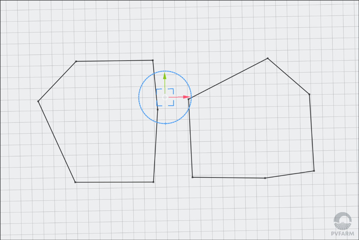
When the ‘Edit’ mode is active all points of selected Boundaries are active
-
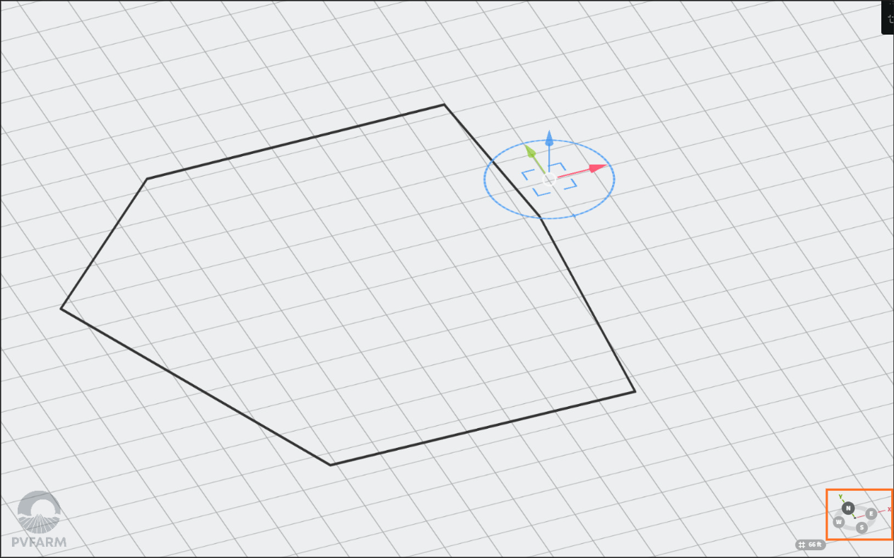
Activate the Gizmo to control points
-
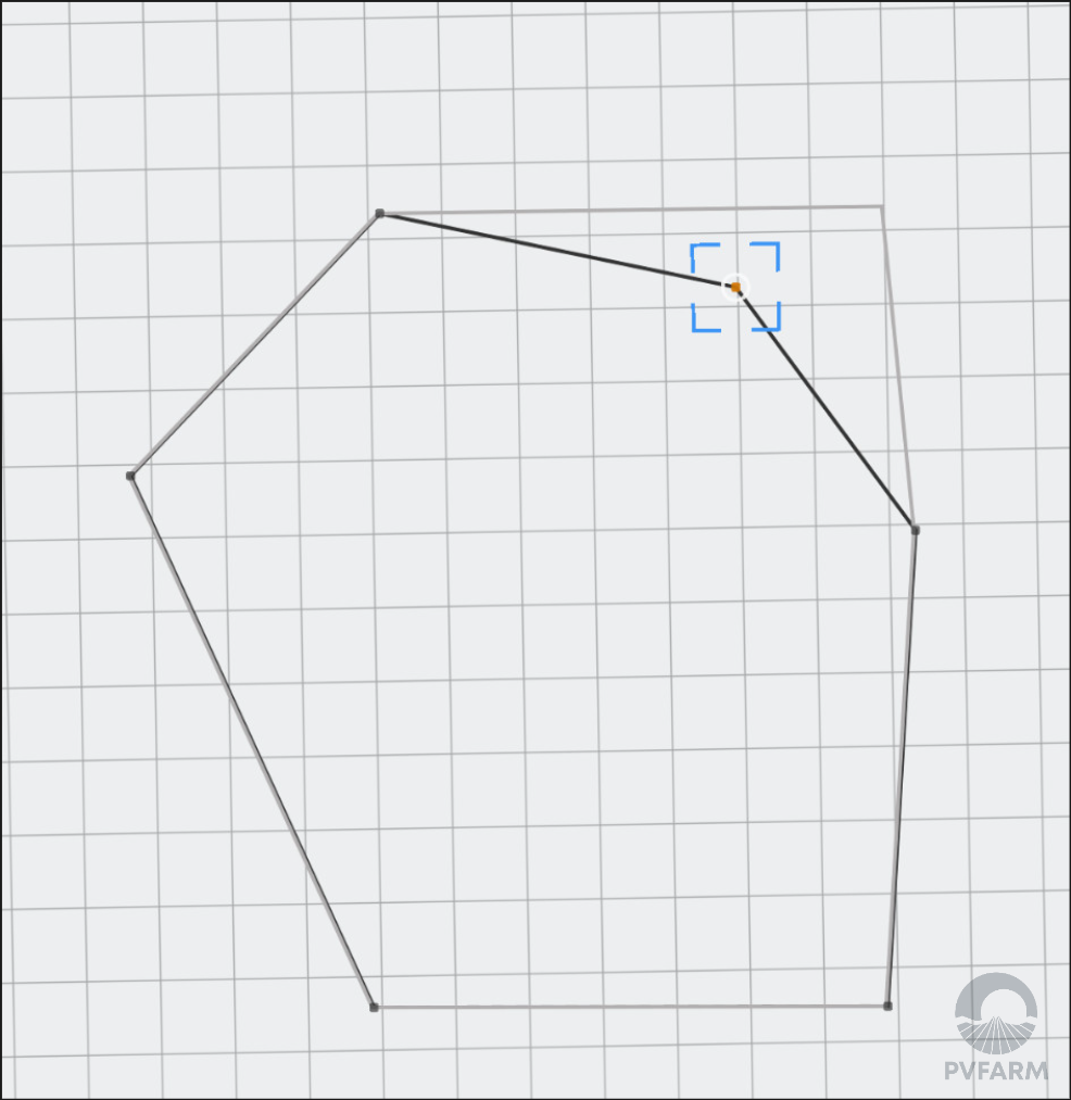
To select a Point tick on it left mouse click
-
For multi-selection use ‘CTRL’ on your keyboard
-
-
Use Red and Green arrows to move a selected point (X and Y axis)
-
Red - left and right (X axis)
-
Green - top and bottom (Y axis)
-
-
Use the blue corners to move in any X-Y direction you want
-
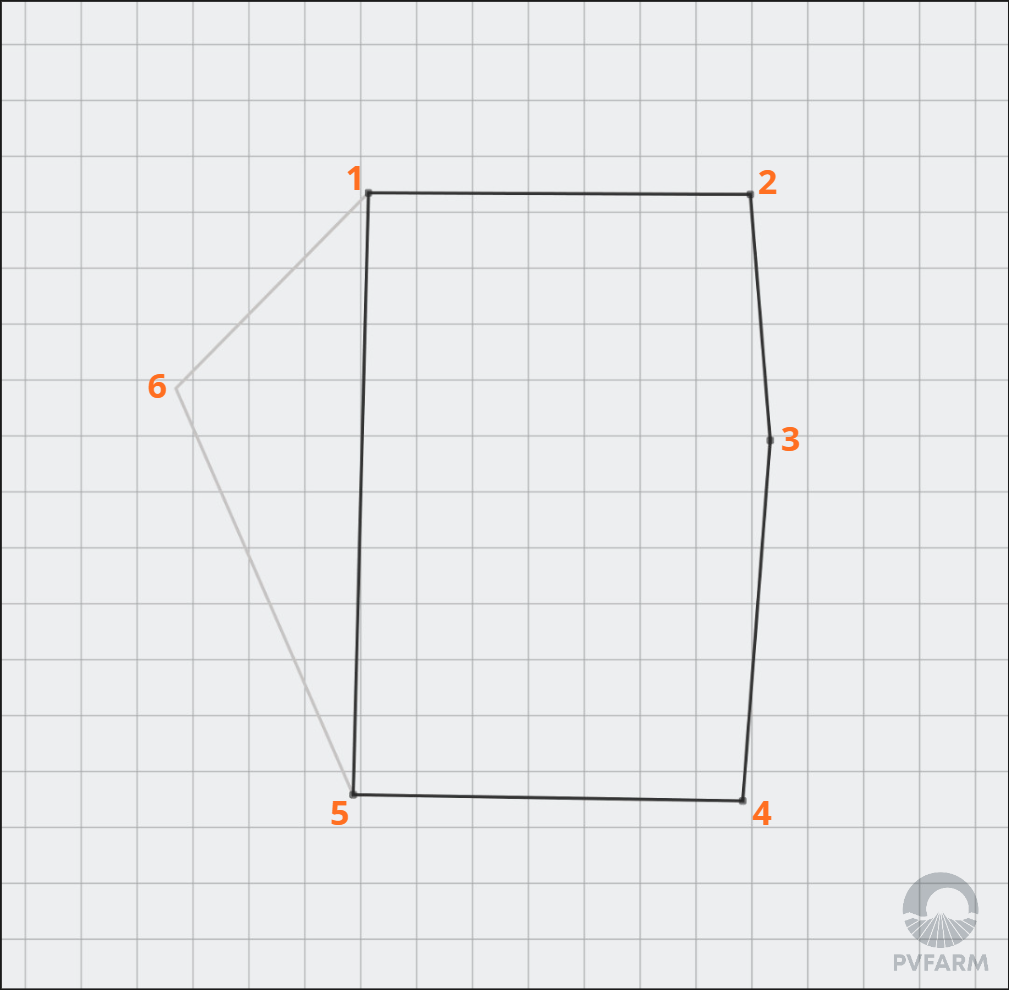
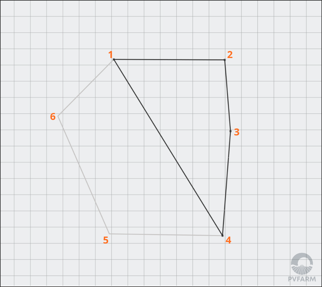
To remove a point you select the point and press 'delete' on your keyboard
-
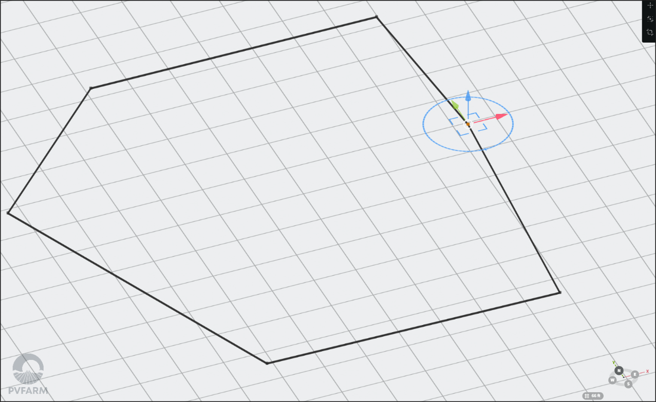
To add a point
-
select the point to the left of where you want your new point to be with the gizmo activated
-
hold 'CTRL' and drag to where you want the new point to be
-
-
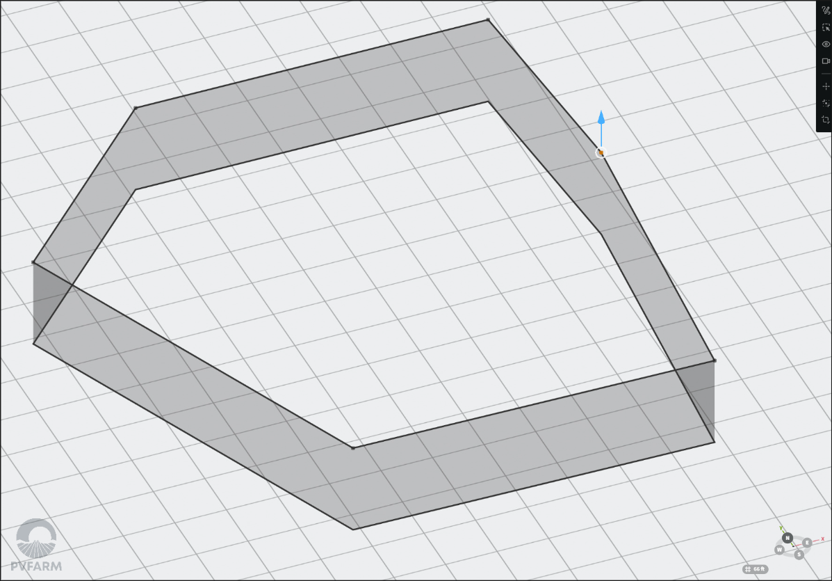
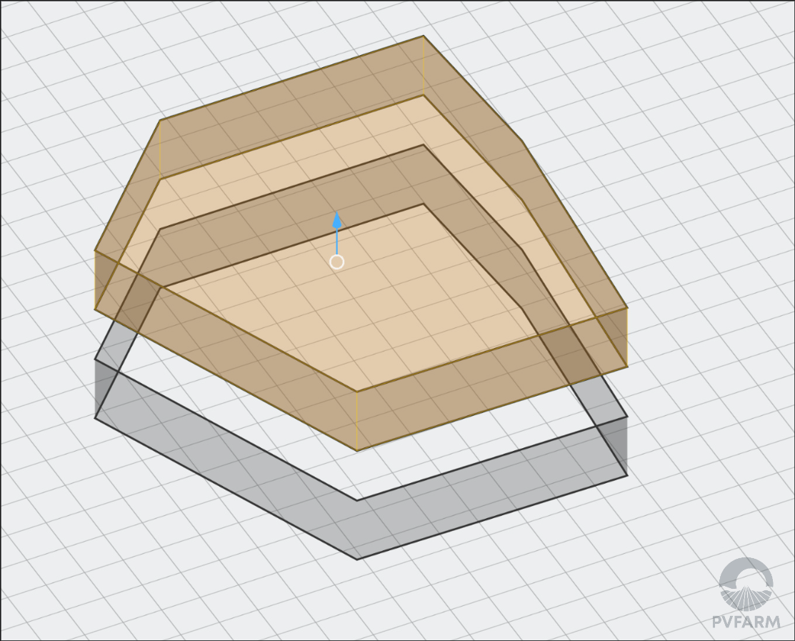
To elevate the boundary line up or down change a view from top to 3D - right mouse motion
-
So now you can see the 3D Gizmo
-
-
Select a Point or any of them (it doesn’t matter how many Points were selected)
-
Move the blue arrow up or down
-
Press ‘ESC’ on your keyboard to exit the ‘Edit’ mode
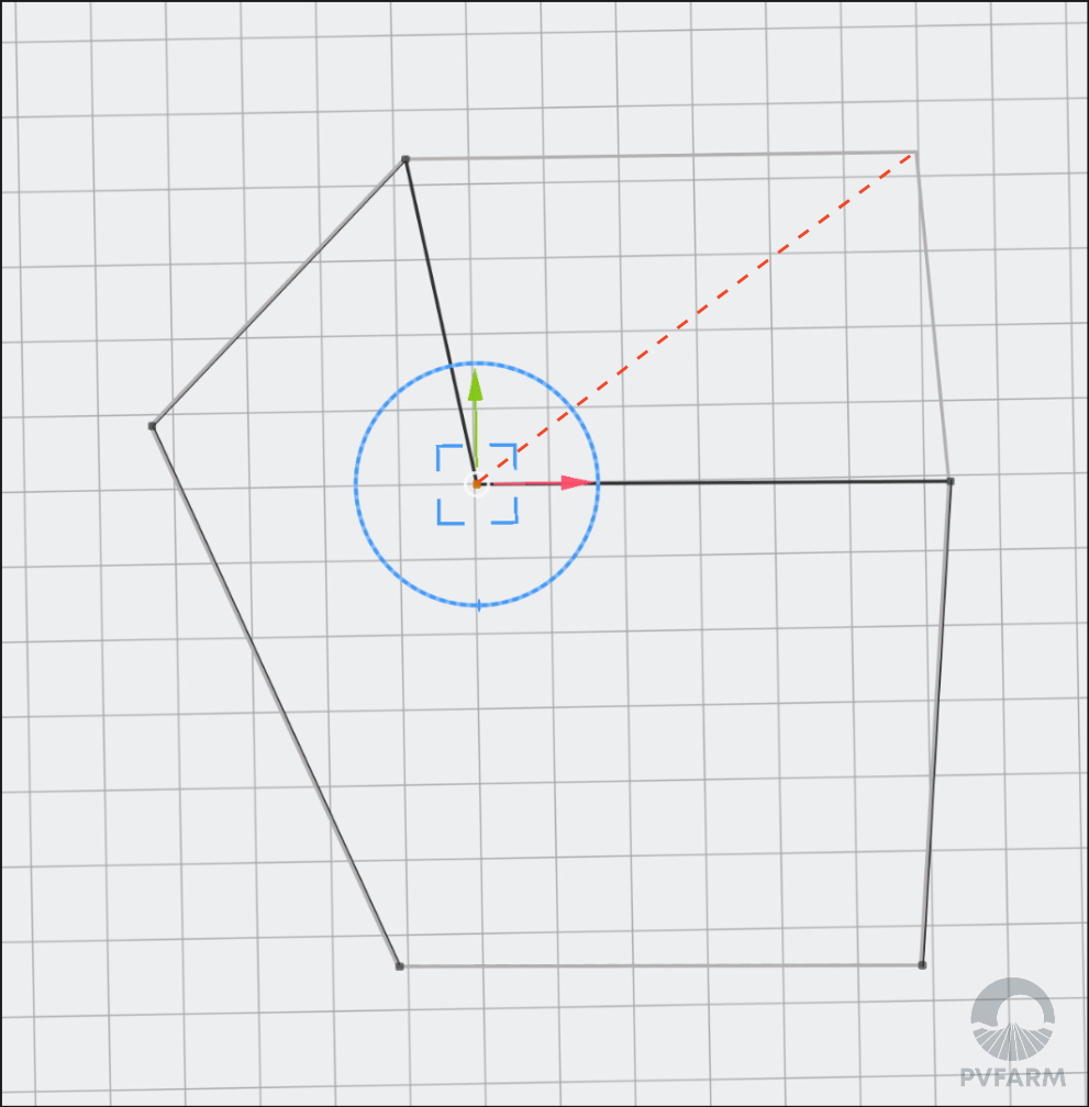
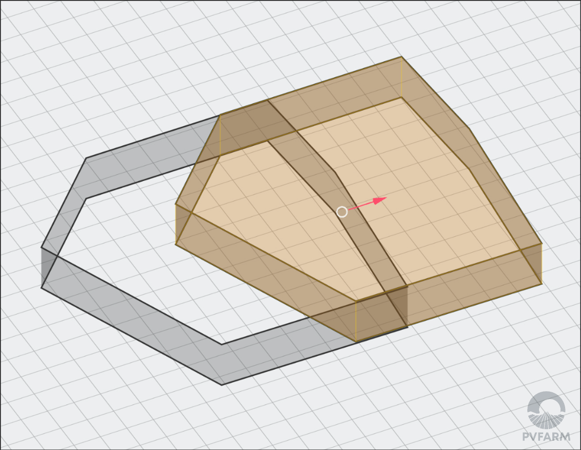
How To Copy Boundaries
-
Select a Boundary from the 3D scene or Model Explorer menu
-
For multi-selection use ‘CTRL’ on your keyboard
-
-
Activate the Gizmo (Press ‘T’ on your keyboard)
-
Press ‘CTRL’ on your keyboard
-
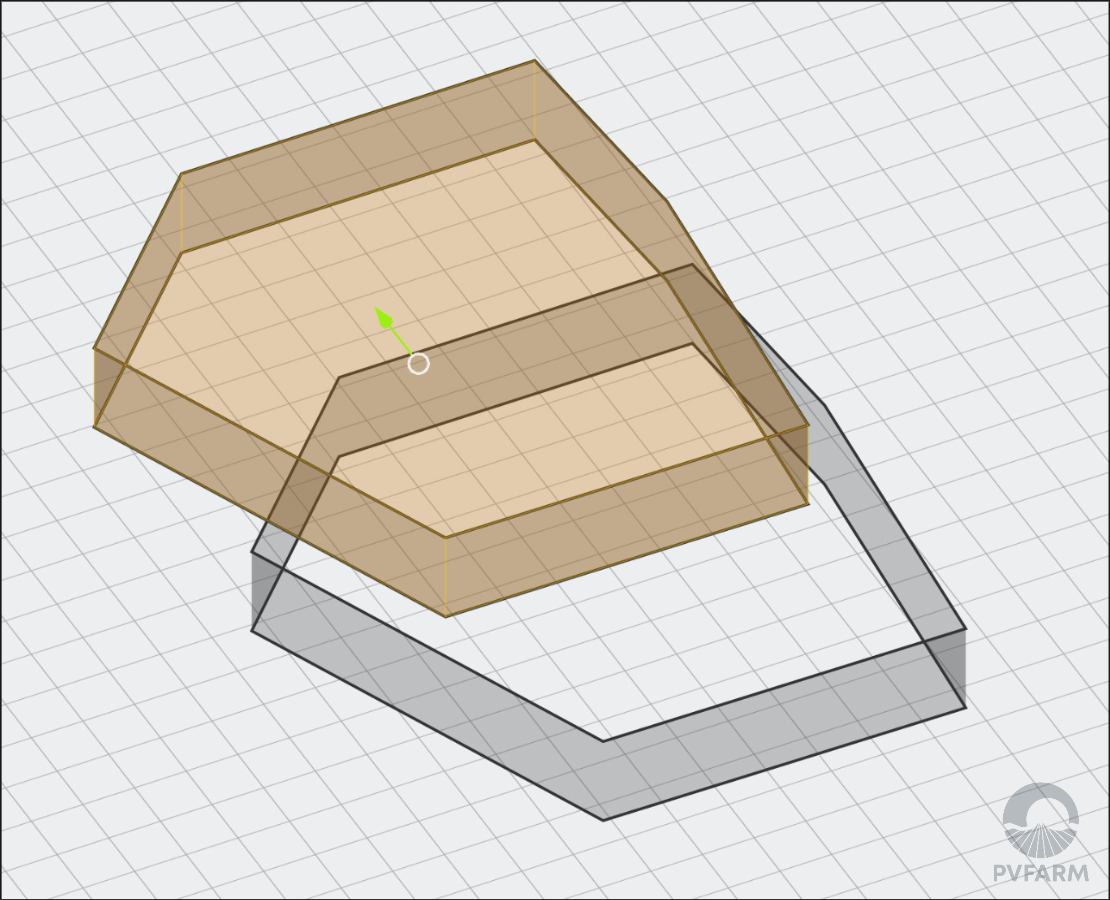
Use one of the Gizmo’s controls
-
The red arrow (X-axis)
-
The green arrow (Y-axis)
-
The blue arrow (Z-axis)
-
How To Delete Boundaries
-
Select a Boundary from the 3D scene or Model Explorer menu
-
For multi-selection use ‘CTRL’ on your keyboard
-
-
Press ‘Delete’ on your keyboard