.png?width=200&height=98&name=Horizontal%20PVFARM%20Logo%20(Small).png)
Low Voltage
The low voltage tab is the method in which PVFARM allows for configuration of the electrical layout from panels to inverters.

- Selected Area - Where PVFARM is going to apply the selected equipment and wiring configurations.
- BC BOS Equipment - The location where PVFARM allows for selection of DC equipment and layout options
- Wiring - PVFARM has numerous options for different LV wiring schematics.
LV Equipment Configuration

- Combiner Box - The DC box selected to be used in the LV design
- Offset from Array - The distance away from the end of a table that the box should be placed
- Safety Factor - Factor to be used in the LV cable sizing.
- Fully Loaded CB's- click on the i icon to see the follow image:
- CB Placement Strategy - How the boxes should be located
- Clustering - What strategy should be used if selected clustered boxes
- CB Position in Arrays Row - Where the boxed should be placed in relationship to the arrays
- Rows Collection Strategy - How many rows tall should be used in the LV configuration
- Multi Array

- Single Array

- Multi Array

Wiring
Refer to "Electrical Patterns Explained" for a detailed discussion on the LV wiring configurations.
- Wiring - Select the LV pattern that should be used in the layout and selection of LV wires. PVFARM has 4 available configurations for LV wiring to select from.
When "Set Wire Gauges by" is set to Voltage Drop:
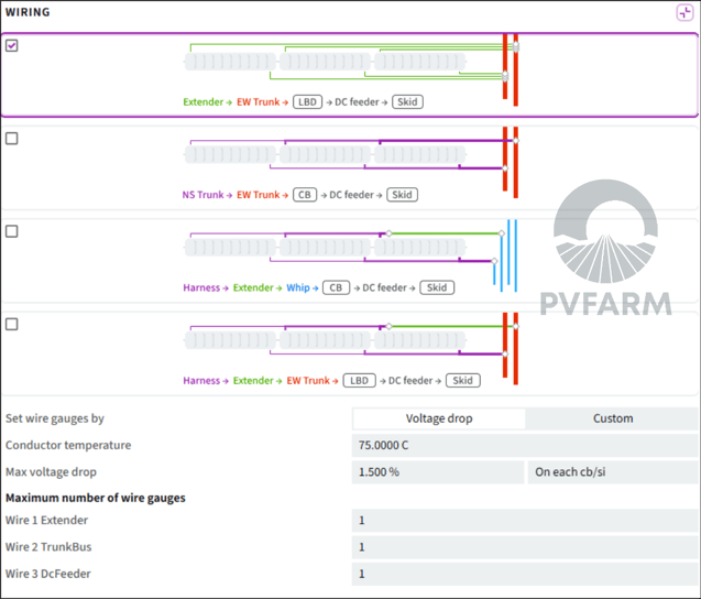
- Set Wire Gauges By - PVFARM allows LV wires to be sized by Voltage Drop or Custom. When voltage drop is selected the conductor temperature and max voltage drop options are available.
- Conductor Temperature - Set the temperature to be used when sizing the cables via Voltage Drop
- Max Voltage Drop - Set the percentage voltage drop to be used in the cable calculations and also select if you want the voltage drop to be dc box or each cable segment
- Maximum Number of Wire Gauges - Tell PVFARM how many different cable sizes it can use for each segment of cable in the project
When "Set Wire Gauges by" is set to Custom:

- Set Wire Gauges By - PVFARM allows LV wires to be sized by Voltage Drop or Custom. When Custom is selected it forces PVFARM to use specific cable sizes for specific wire segments.
- Conductor Temperature - N/A when selecting Custom
- Max Voltage Drop - N/A when selecting Custom
- Maximum Number of Wire Gauges - Tell PVFARM what cables to use for each wire type required in the wiring selection.
Enable wire offset
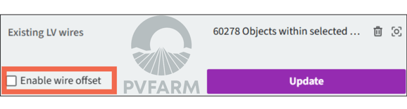
Selecting the wire offset separates the wires in the 3d model space.
Without "Enable Wire Offset" checked

With "Enable Wire Offset" checked

Medium Voltage
Substations-a drop down list of available substations in the project that you want to run MV for.
Exclude Boundaries- Select boundaries where MV can not be run through.
Wiring
Equipment
- Sectionalize Cabinet- a drop down list of available sectionalizing cabinets to be used.
MV Wires
- Above Ground- Check this if you want your wires run above ground
- Temperature- Define the desired temperature for your wires
- Wires- Select all wires that you want included in MV generation, remove options that you do not want included.
Settings
- Max Voltage Drop- Define the maximum average voltage drop for your circuit.
- Max Power MV Circuit- define the max power for your circuit.
- Bias- A sliding scale to have the algorithm prioritize less wires or less trenches.
Routing
Waypoints
- Waypoints are points that can be added to your layout that will direct the route of nearby MV wires.
- + Add Waypoint- will enable Add mode for Waypoints, you can continue to add Waypoints until pressing "Ok"
Circuits
- In this section you can dictate which block numbers are together in one circuit
- +Add Circuit- will create one section with a drop down, select all blocks that you want included in that circuit.
Trenches
This is where you can define the size of your trenches, you can define the space between wires and a minimum trench depth. To learn more see the article How Trenches Work