.png?width=200&height=98&name=Horizontal%20PVFARM%20Logo%20(Small).png)
What to consider before creating an SAT (Single-Axis Tracker)
When creating your SAT objects it is important to understand the required dimensions and information required to make the Objects.
- Modules to be used (make sure it has already been added to the catalog).
- Number of modules in a string.
- Total number of strings on the SAT.
- Total length (This is very important as the length is how PVFARM will place the SAT's onsite)
- Any gaps (motors, piles, etc.)
- Pile locations (Critical when doing advanced piles and grading).
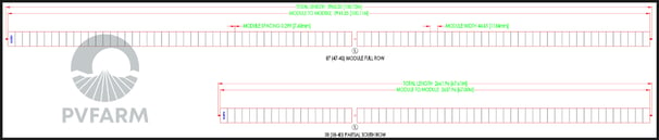
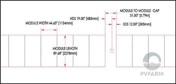
Example of tracker drawings with the information required to setup the SAT:
Creating your SAT
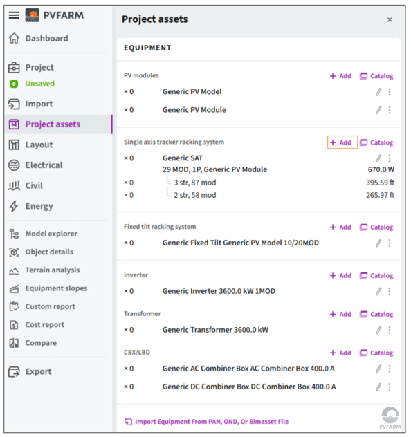
To create a SAT in PVFARM, create a new series in the Project Assets panel.
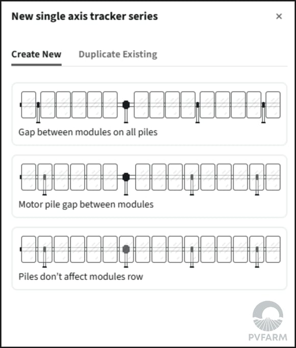
SAT creation wizard
After selecting either option, a creation wizard will open up. First it will ask you about the gaps in your new SAT. Are there gaps between the modules for all piles? Just the motor piles? Or are there no gaps? Select the option that you prefer.
Next the wizard will ask you some basic info about your new SAT.
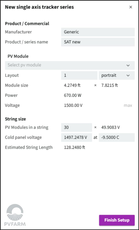
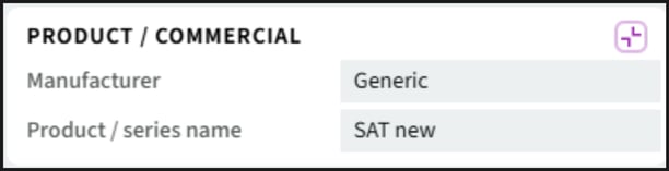
- Product/Commercial
- It is very import to enter your commercial SAT info here. When you add the SAT to the catalog the standard naming will be:
Manufacturer -> Model -> Module - For each of those configuration you will have the option to select all available tracker configurations (string lengths and number of strings) when using the layout panel. The name of the tracker will appears after the string/total length in the tracker configurations, it does not affect the selection of the trackers.
- It is very import to enter your commercial SAT info here. When you add the SAT to the catalog the standard naming will be:
- Module
- Use the drop down that appears under pv-module to select the module from your catalog that you would like to use when setting up this SAT.
- The remainder of the module properties will be added based on that module.
- You have the ability to adjust your module profile and orientation, everything else will be automatically calculated based on the information that lives in the module catalog item.
- Use the drop down that appears under pv-module to select the module from your catalog that you would like to use when setting up this SAT.
- String Size
- This is where you'll determine the amount of modules per string. Don't worry about amount of strings at this point, we'll get to that next.
- You can also enter the cold panel voltage if you know it, or leave it as a default.
Modify your SAT
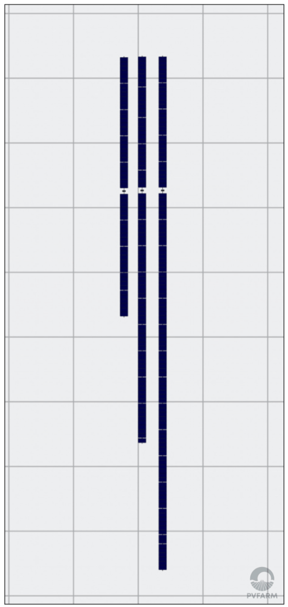
After clicking "Finish Setup", three lengths of SATs will be placed in your scene. Once the SAT objects are in the scene you will be able to see them in your Project Assets, click on the equipment in Project Assets to begin to refine the parameters for your SAT series.

If you want your motors to align when generating layout, ensure that motor piles are lined up in this view.
Series and Models
Your SAT objects consist of the overall series, and models within that series. Your models will be different string sizes of that tracker series.

You can add, remove, or change the models in your series by clicking anywhere on the SAT section of your Project Assets panel.

From this menu you will be able to make adjustments to the individual models within your series by clicking on the pencil (or edit) icon. You can change up the string counts of the three lengths that were automatically created, or click on "Add New Model" to add another length.
Single Axis Tracker Editing Panel
Here is where you'll edit the properties for all models in your SAT series

1. Product/ Commercial
This is where you'll input the manufacturer and product information for your tracker
2. PV Modules

This is where you'll input the module which will need to be added to your catalog before editing your tracker. To learn how to do that see this article. You'll also be able to edit the module mounting, orientation, and string information for your SAT series.
3. Model Configuration
This is where you can edit the details of each individual model within your SAT series, you can press the arrows to move from one model to the next. Be sure to click on "Apply Changes" or "Revert Changes" at the bottom of the menu before moving to the next.

Specify Gaps between Modules
This is where you'll define the various gaps in this particular model of your tracker. Toggle this section off if you do not have this information yet/ don't want to make adjustments to your gaps.

Exact Piles Placement
This is where you'll define the pile types and placement for each wind load variant of your tracker model. Toggle this section off if you do not have this information yet/ don't want to make adjustments to your piles.