.png?width=200&height=98&name=Horizontal%20PVFARM%20Logo%20(Small).png)
1. Conductor size
In the United States and Canada, conductor sizes are conventionally specified using the American Wire Gauge (AWG) system for smaller cross-sectional areas and the KCMIL system for larger sizes. In Europe, conductor sizes are defined by their cross-sectional area expressed in square millimeters, with the available sizes comprehensively listed in IEC 60228. These standards provide an exhaustive classification of conductor sizes.
| U.S. Standard | Equivalent cross-section (mm²) | Nearest available cross-section (mm²) | IEC 60228 Conductor Size |
| 20 AWG | 0.519 | 0.5–0.75 | 0.5–0.75 mm² |
| 18 AWG | 0.823 | 1.0 | 1.0 mm² |
| 16 AWG |
1.31 | 1.5 | 1.5 mm² |
| 14 AWG | 2.08 | 2.5 | 2.5 mm² |
| 12 AWG | 3.31 | 4.0 | 4 mm² |
| 10 AWG | 5.26 | 6.0 | 6 mm² |
| 8 AWG | 8.37 | 10 | 10 mm² |
| 6 AWG | 13.30 | 16 | 16 mm² |
| 4 AWG | 21.15 | 25 | 25 mm² |
| 2 AWG | 33.62 | 35 | 35 mm² |
| 1 AWG | 42.41 | 50 | 50 mm² |
| 1/0 AWG | 53.49 | 70 | 70 mm² |
| 2/0 AWG | 67.23 | 70 | 70 mm² |
| 3/0 AWG | 85.01 | 95 | 95 mm² |
| 4/0 AWG | 107.2 | 120 | 120 mm² |
| 250 KCMIL | 126.7 | 120–150 | 120–150 mm² |
| 300 KCMIL | 152.0 | 150 | 150 mm² |
| 350 KCMIL | 177.3 | 185 | 185 mm² |
| 400 KCMIL | 202.7 | 185 | 185–240 mm² |
| 450 KCMIL | 228.0 | 185–240 | 185–240 mm² |
| 500 KCMIL | 253.4 | 240 | 240 mm² |
| 550 KCMIL | 278.7 | 240–300 | 240–300 mm² |
| 600 KCMIL | 304.0 | 300 | 300 mm² |
| 650 KCMIL | 329.4 | 300 | 300 mm² |
| 700 KCMIL |
354.7 | 300–400 | 300–400 mm² |
| 750 KCMIL | 380.0 | 400 | 400 mm² |
| 800 KCMIL | 405.4 | 400 | 400 mm² |
| 850 KCMIL | 430.7 | 400 | 400 mm² |
| 900 KCMIL | 456.0 | 400 | 400 mm² |
| 950 KCMIL | 481.4 | 400 | 400–630 mm² |
| 1000 KCMIL | 506.7 | 400–630 | 630 mm² |
| 1250 KCMIL | 633.4 | 630 | 800 mm² |
| 1500 KCMIL | 760.0 | 800 | 800–1000 mm² |
| 1750 KCMIL | 886.7 | 800–1000 | 1000 mm² |
| 2000 KCMIL | 1013.4 | 1000 | 1000 mm² |
In other jurisdictions, the method of defining conductor sizes and the range of available conductors may deviate from the practices adopted in the United States and Europe.
PVFARM Solution
In PVFARM, support for different conductor types and sizes is provided through the creation of wire BIM assets in the Catalog.
The Catalog includes a predefined set of conductors in compliance with both American and European standards.
Within the Catalog, the user first selects the standard (AWG for the USA or EWG for Europe). For the selected standard, the appropriate gauge and material can then be chosen. The conductor diameter is calculated automatically based on the selected gauge.
For each gauge, the user may specify custom parameters such as DC & AC resistance at 25°C and the temperature-dependent current rating for conductors installed either underground or in open air. Once defined, these parameters can be saved in the Catalog as a new wire BIM asset.
2. DC Resistance of LV wires
In accordance with the NEC (National Electrical Code) standard used in the USA, the DC resistance values for conductors are specified at a temperature of 75°C (CHAPTER 9 – Table 8. Conductor Properties).
For other temperature values, resistance is recalculated using the following formula:
where, for copper conductors, α=0.00323 , and for aluminum conductors, α=0.00330.
In accordance with the European standard, in PV systems the LV wires connecting strings to combiner boxes and string inverters are copper conductors, metal-coated, Class 5. For such conductors, the DC resistance is specified in EN 60228 at a reference temperature of 20°C.
For LV conductors connecting the Combiner Boxes and the Central Inverter, Class 2 conductors are used, and their DC resistance is specified at 20°C.
For recalculating the resistivity at different temperatures, the EN 60228 standard uses the following formula:
where:
R1— is the DC resistance of the conductor at 20 °C (Ω/m);
α — is the constant mass temperature coefficient at 20 °C (see Table below).
T — is the maximum operating temperature in degrees Celsius (this will be determined by the type of insulation to be used).
PVFARM Solution
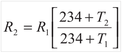
To avoid storing resistance values for each standard at its own reference temperature and recalculating them with different formulas, PVFARM normalizes all conductor resistance values to 25 °C. Subsequent adjustments for other temperatures are then performed using the following formulas:
1. for copper wires:

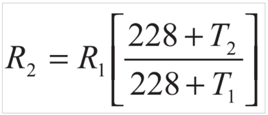
2. for aluminum wires:

It is assumed that Class 2 conductors are required only for aluminum wires (so that it is not necessary to define separate resistance values for copper conductors of both Class 5 and Class 2). In practice, the resistance of copper conductors in Class 5 and Class 2 differs by no more than 5%.
3. AC resistance of LV wires
In accordance with the NEC (National Electrical Code) standard, AC resistance values are specified at a temperature of 75°C (CHAPTER 9 – Table 9. Conductor Properties).
In the European standard IEC 60287-1-1, the AC resistance of conductors is calculated on the basis of their DC resistance using the following formulas:


PVFARM Solution
In PVFARM, for each conductor gauge the AC resistance value is determined at 25 °C. For American conductors, this is done by recalculating the AC resistance specified at 75 °C down to 25 °C. For European conductors, the calculation is carried out using the formulas provided in the European standards referenced above.
Subsequently, when determining the conductor losses under alternating current, the AC resistance value obtained at 25 °C is further adjusted to the permissible operating temperature of the conductor."
4. Reactance
The total impedance of a conductor under alternating current is defined by the following expression:
Z = AC Resistance * Power Factor + Reactance * sin[ arccos(*Power Factor) ]
This expression effectively determines the effective resistance of the line at a given power factor, taking into account both the ohmic losses and the reactive component of the conductor.
In accordance with the NEC (National Electrical Code) standard, reactance values are provided in CHAPTER 9 – Table 9 (Conductor Properties).
In the European standard, the reactance is calculated using the following formula:
where:
ω - frequency, 1/s;
s — is the distance between conductor axes in the electrical section being considered (mm);
d — is the mean diameter of the sheath (mm).
5. Current carrying capacity
In the NEC standard, there are numerous tables specifying the permissible current depending on conductor temperature, installation method, ambient temperature, and other factors.
In PVFARM, when creating BIM assets for conductors, a simplified approach was applied: one installation option for conductors above ground with different temperature ratings (60, 75, and 90 °C), and one installation option for conductors underground with different temperature ratings (60, 75, and 90 °C). At the same time, the user can edit these values within the BIM asset.
For underground conductors, the following table was used:
For conductors installed in air, the following table was used:
The European standard IEC 60287-1-1 provides a methodology for calculating the permissible current in a conductor based on its temperature and various installation conditions. On the other hand, the European standard IEC 60364-5-523 already includes calculated permissible current values for LV wires under many installation scenarios.
For underground installations, the most relevant tables are Table 52-C3 for a conductor temperature of 70 °C and Table 52-C4 for a conductor temperature of 90 °C.

For installations in air, the most relevant tables are Table 52-C9 and Table 52-C10 for a conductor temperature of 70 °C, and Table 52-C11 and Table 52-C12 for a conductor temperature of 90 °C.


Accordingly, in PVFARM, based on these tables, the permissible current values at 70 °C and 90 °C are predefined for the default BIM asset conductors.
When generating an LV wire, the user can specify a custom temperature value. In that case, the permissible current is determined by interpolation.
6. Loss Calculation
1. For existing wire gauge, the respective DC Resistance value is adopted.2. Recalculate the wire resistance value for the specified wire temperature:
a. for copper wires:
b. for aluminum wires:
3. For conductors carrying alternating current (from the string inverter to the transformer), the AC resistance and reactance for the corresponding wire gauge are taken from the table. The AC resistance value is then adjusted to account for the conductor temperature.
4. The total resistance of the conductor will be:
a. for direct current (DC):
Resistance = DC Resistance
b. for alternating current (AC):
Resistance = AC Resistance * Power Factor + Reactance * sin[ arccos(Power Factor) ]
By default, the Power Factor is set to 0.95.
5. The conductor losses are calculated as follows:
1. for direct current (DC):
Losses = 2 * Current * Current * Length * Resistance
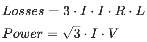
2. for alternating current (AC):
Losses = 3 * Current * Current * Length * Resistance
7. Voltage Drop Calculation
DC circuits
In the NEC and European standard, the formula used to calculate voltage drop in percentage:
We multiply the numerator and denominator by the current (I) and obtain:
where:

AC circuits
In the NEC and European standard, the formula used to calculate voltage drop in percentage:
We multiply the numerator and denominator by the √3⋅I and obtain:
where:
8. Conductor Sizing
When the user selects the "wire gauge selection" option, the automatic gauge selection is performed as follows:
1. For the material specified by the user, a gauge is automatically selected so that the current in the wire does not exceed the allowable current for that gauge.
2. Depending on the user's choice, a check is performed to ensure that either:
- the voltage drop in each wire does not exceed the user-specified voltage drop, or
- the power-weighted average voltage drop across the combiner boxes does not exceed the user-specified voltage drop.