.png?width=200&height=98&name=Horizontal%20PVFARM%20Logo%20(Small).png)
These patterns will affect your layout significantly as PVFARM will attempt to optimize the tracker layout to minimize cabling for each scheme.
The details of the patterns are below.
When setting up the electrical blocking PVFARM provides the option to select the type and size of the inverter. PVFARM supports both central and string inverters. When selecting the electrical blocks the inverter and transformers can be selected from any equipment available in the catalog. Refer to the layout knowledgebase article for a full description of all inputs in the layout window.

Low Voltage Tab
The low voltage tab is the method in which PVFARM allows for configuration of the electrical layout from panels to inverters.

- Selected Area - Where PVFARM is going to apply the selected equipment and wiring configurations.
- BC BOS Equipment - The location where PVfarm allows for selection of DC equipment and layout options
- Wiring - PVFARM has numerous options for different LV wiring schematics.

- Combiner Box - The DC box selected to be used in the LV design
- Offset from Array - The distance away from the end of a table that the box should be placed
- Safety Factor - Factor to be used in the LV cable sizing.
- Fully Loaded CB's - Fully loaded CB's will connect arrays outside of a vertical only configuration to maximize the power on each CB. Straight will keep CB groupings in a continuous vertical array arraignment.
- CB Placement Strategy - How the boxes should be located
- Distributed

- Clustered

- Distributed
- Clustering - What strategy should be used if selected clustered boxes
- Full

- Partial
- Full

-
- CB Position in Arrays Row - Where the boxed should be placed in relationship to the arrays
- Rows Collection Strategy - How many rows tall should be used in the LV configuration
- Multi Array

- Single Array

- Multi Array

DC Box Layout
Distributed-Middle-Single

Distributed-Middle-Multi

Distributed-End of Row-Single

Distributed-End of Row-Multi

Clustered-Partial-Middle-Single

Clustered-Partial-Middle-Multi

Clustered-Partial-End of Row-Single

Clustered-Partial-End of Row-Multi

Clustered-Full-Middle-Single (Same as End of row as full clustering places Boxes near the Inverter)
Clustered-Full-Middle-Multi (Same as End of row as full clustering places Boxes near the Inverter)
Clustered-Full-End of Row-Single

Clustered-Full-End of Row-Multi

String Inverter Wiring
The pattern with Multi-harness and String inverter - Multi-Harness is the only option for string inverters

Central Inverter Wiring
Extender - EW Trunk - LBD - DC Feeder - Skid

Extender - EW Trunk - LBD - DC Feeder - Skid

Extender - EW Trunk - LBD - DC Feeder - Skid

Extender - EW Trunk - LBD - DC Feeder - Skid

Central Inverter Wiring
Below is an explanation of how the wiring configurations work in PVFARM. Shown is one example for Extender - EW Trunk - LBD - DC Feeder - Skid. Each wiring configuration will have specific wire types that correspond to the wiring diagrams.
When "Select Wire Gauges by" is set to Voltage Drop
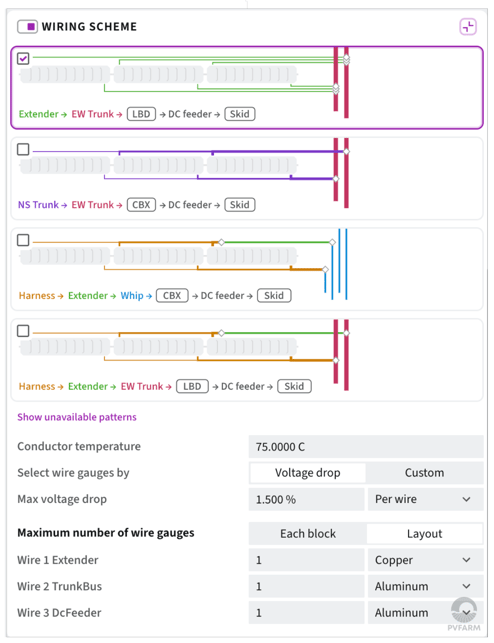
- Select Wire Gauges By - PVFARM allows LV wires to be sized by Voltage Drop or Custom. When voltage drop is selected the conductor temperature and max voltage drop options are available.
- Conductor Temperature - Set the temperature to be used when sizing the cables via Voltage Drop
- Max Voltage Drop - Set the percentage voltage drop to be used in the cable calculations and also select if you want the voltage drop to be dc box or each cable segment
- Maximum Number of Wire Gauges - Tell PVFARM how many different cable sizes it can use for each segment of cable in the project
When "Select Wire Gauges by" is set to Custom

- Select Wire Gauges By - PVFARM allows LV wires to be sized by Voltage Drop or Custom. When Custom is selected it forces PVFARM to use specific cable sizes for specific wire segments.
- Conductor Temperature - N/A when selecting Custom
- Max Voltage Drop - N/A when selecting Custom
- Maximum Number of Wire Gauges - Tell PVFARM what cables to use for each wire type required in the wiring selection.