.png?width=200&height=98&name=Horizontal%20PVFARM%20Logo%20(Small).png)
You can import an AutoCAD drawing into PVFARM without renaming its layers. During import, PVFARM detects the drawing’s layers and objects, suggests how they should be mapped, and lets you review the assignments before adding them to your project.
This guide explains how to prepare your file, review layer mappings, and verify imported equipment.
Before you begin
Save your AutoCAD drawing as a DXF file. You can keep your existing layer names.
Keep the original drawing available during import so you can check tracker dimensions and configurations when needed.
1. Add your DXF file
Create a new project in PVFARM, give it a name, and drag and drop your DXF file into the project.
Review the detected coordinate reference system (CRS) and location, then select Start a project.
2. Review layer mappings
In the import window, open Layers and Objects. This tab shows the layers detected in your drawing and how they are assigned to PVFARM object types.
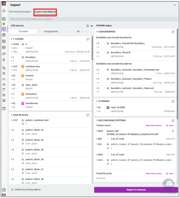
PVFARM suggests mappings automatically. Hover over items to highlight them in the preview and check that each layer is assigned correctly.
To change an assignment, drag the layer into the appropriate category. For example, move a boundary from Exclusion Zones to Buildable Areas if it represents an area where equipment can be placed.
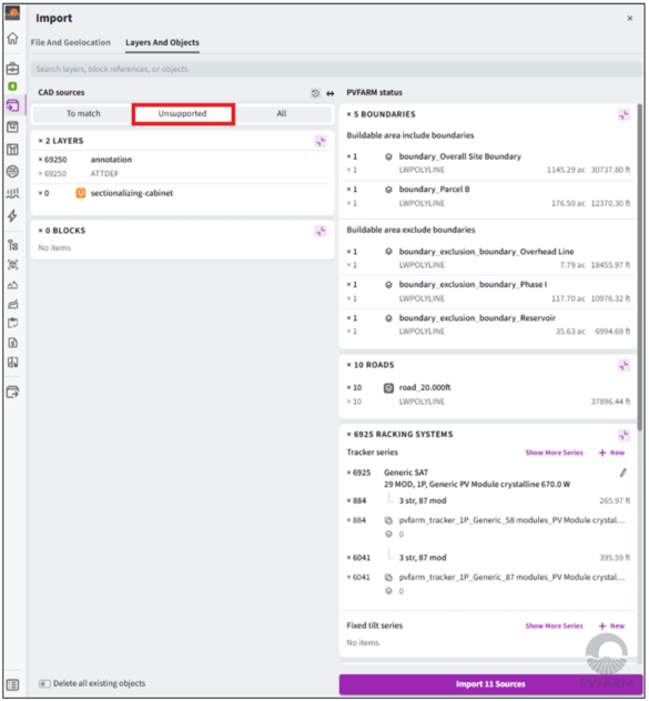
If you can’t find a layer in the list, check the Unsupported tab. Layers may appear there because they contain unsupported content, such as annotations, or because no objects were detected.
3. Verify tracker configurations
Review the equipment matched to your tracker layers. If a suggested match is incorrect, select another equipment option or choose New to create a tracker series.
Check the displayed dimensions against your AutoCAD drawing, particularly when the layout contains trackers of different lengths. This helps ensure that the imported equipment matches the original layout.
If different tracker sizes have been assigned the same configuration:
- Select the edit icon for the project asset.
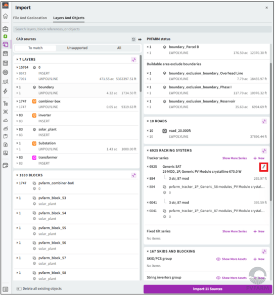
- Open the tracker configuration you need to correct.
- Update the configuration to match the drawing.
- Apply the changes and check the preview.
4. Check the remaining objects
Before importing, review the other objects detected in your drawing:
| Object | What to check |
|---|---|
| Boundaries | Confirm that buildable areas and exclusion zones are assigned correctly. |
| Roads | Review the layers containing road centerlines. |
| Inverter skids and blocking | Check their assignments and positions in the preview. |
| Substation | Verify the location detected in the drawing. |
| Terrain isolines | Confirm that the correct contour layers are included. These will be converted into terrain. |
| 3D shade objects | Review any detected shade objects you want to include. |
You can import inverter skids at their existing locations before assigning them to trackers.
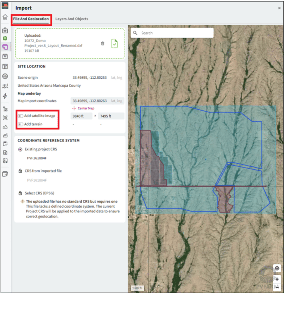
To add satellite imagery or additional terrain, use Files and Geolocation in the import window.
5. Import your sources
Once you’ve reviewed the layer mappings and equipment configurations, select Import Sources.
On your first import, PVFARM asks for permission to use AI to learn the relationship between your layer names and PVFARM object types. Allowing this helps PVFARM recognize those mappings in future imports and reduces the amount of manual setup.
6. Review the imported project
Check the imported layout to confirm that the equipment, boundaries, roads, and terrain appear as expected.
Inverter skids imported from the drawing may still need to be assigned to trackers. Complete those assignments and any necessary manual modeling to preserve the inverter locations from your original layout.