Creating Boundaries Based on Terrain in PVFARM
How to create boundaries based on your project's terrain
In this article, we will guide you through the process of creating boundaries based on your project’s terrain in PVFARM.
Analyzing terrain based on slope or elevation
Step 1: Analyzing Terrain
-
Import Terrain and Boundary:
-
Ensure you have your terrain and site boundary imported into PVFARM.
-
-
Auto-Fill Ranges and Colors:
-
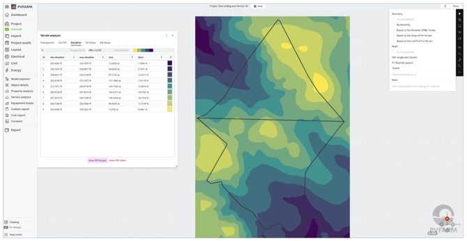
Use the auto-fill feature to populate ranges and colors for your terrain.
-
-
Adjust Terrain Ranges:
-
To customize terrain ranges:
-
Set the range count. For example, setting it to 3 will split the terrain into three sections.
-
Manually adjust the ranges if needed. For example, you can set ranges from 0 to 10 feet, 10 to 15 feet, etc.
- selecting which color pallet is preferred for the visualization
-
-
-
Maximize Terrain Overview:
-
Set the range count to 10 (the maximum) for the most detailed breakdown.
-
Step 2: Create Boundaries Based on Terrain
1. Create the Boundaries:
-
Click on the plus sign next to “Boundary” and select “Based on the Elevation of the Terrain” or “Based on the NS Slope of the Terrain.”
- Click on the plus sign next to "Boundary" and select "Based on the cutfill of the terrain" if you have a cut fill surface created in the project.

-
You can see that the system has automatically filled in the lowest and highest points of elevation or slope.
2. Set Elevation or Slope Slices:
-
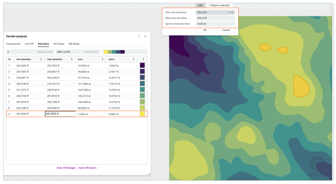
Refer to your terrain analysis panel to set the minimum and maximum elevation for your exclusion zone.
-
Example: For a specific slice represented by a yellow color, set the minimum to 302.0560 feet and the maximum to 309.3832 feet.
-
Use the “Ignore areas less than” option to avoid creating boundaries for tiny areas.
3. Adjust Boundaries:
-
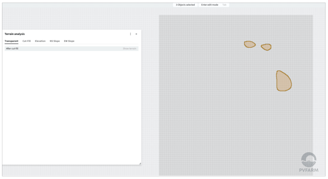
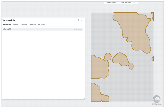
Turn the terrain to transparent to visualize the boundaries that were created.
-
Adjust the “Ignore areas less than” value if needed to capture smaller areas.
Step 3: Utilizing Exclusion Zones
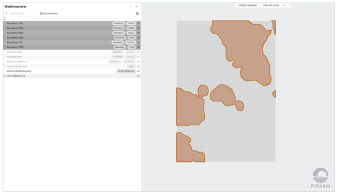
1. Open Model Explorer:
-
Select the newly created boundaries.
-
If they aren’t selected, hold down Shift and select them manually.
2. Set as Exclusion Zones:
-
Go to “Object Details” and change the color to red.
-
Change boundary type to exclusion.
3. Expand Exclusion Zones:
-
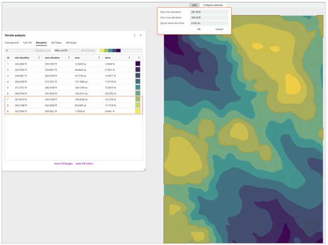
If needed, include more terrain ranges (e.g., light green areas).
-
Click on the plus sign “Based on Terrain” and adjust the min elevation accordingly.
-
Turn the terrain to transparent to see the new boundaries.
Step 4: Utilizing Sub-Areas
-
You can also use these boundaries to create sub-areas for different purposes.
-
Assign different equipment or parameters to these sub-areas.
-
Example: Use terrain-following trackers for specific sub-areas.
-
Analyzing terrain based on cut and fill areas
Step 1: Analyzing Terrain
-
Create cut and Fill surface in PVFARM (Refer to other articles in knowledge center about creating cut-fill surfaces)
- Select Cut-Fill in terrain analysis

Step 2: Create Boundaries Based on Cut and Fill
1. Create the Boundaries:
-
Click on the plus sign next to “Boundary” and select “Based on the cutfill of the terrain.”
-
You can enter the elevations of the cut-fill surface that should be used to create boundaries.
- You can use the +- next to the elevations to select the cut and fill identified in the model

2. Set Cut and Fill slices:
-
Cut Areas

- Fill Areas

By following these steps, you can efficiently manage your project’s terrain and optimize the layout generation process in PVFARM.
.png?width=200&height=98&name=Horizontal%20PVFARM%20Logo%20(Small).png)